Minibot
I'm building a Pololu Romi + Raspberry Pi that will do... I'm not quite sure what, yet.
This is one of many kits owned by a FIRST Robotics team in Canada, donated generously by a U.S. robotics company. This page will likely serve as some basic guidance (alongside the existing online documentation) and some lessons learned about the process. We're going to try to do some basic vision work with the Raspberry Pi camera.
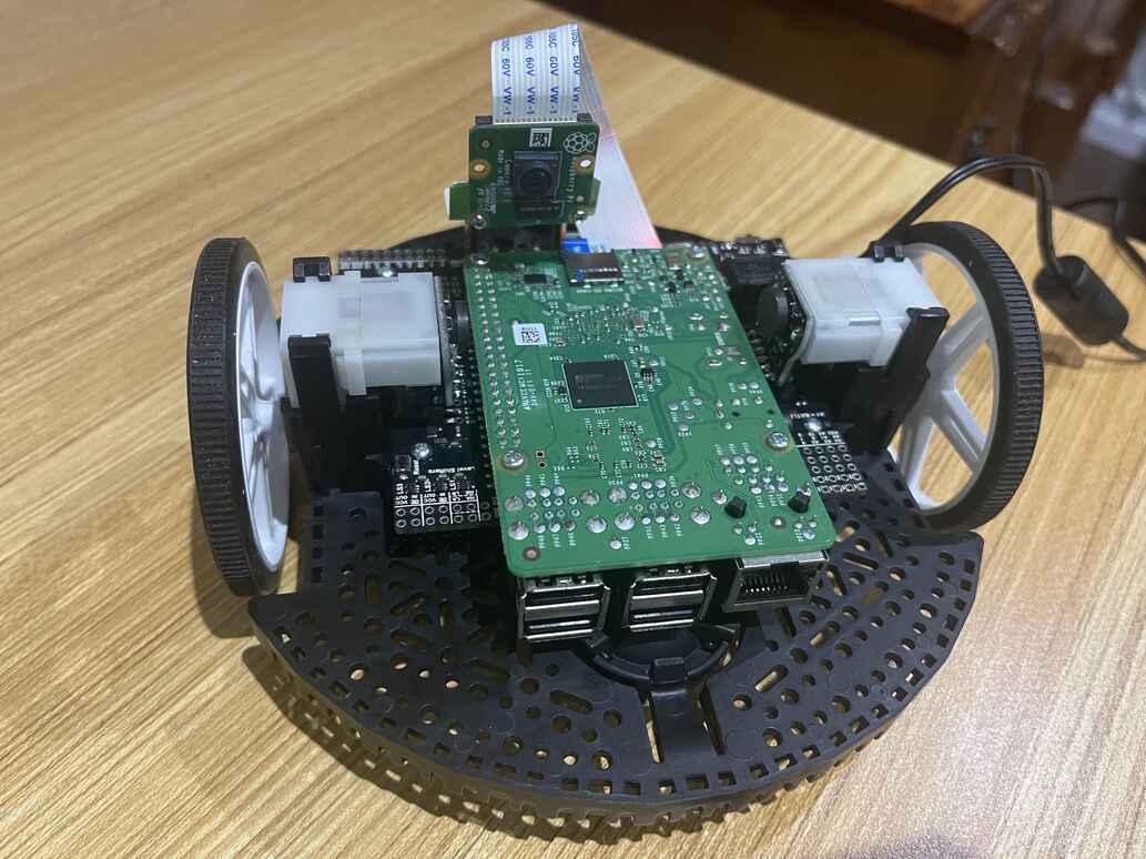
Hardware
The hardware can be separated into three distinct groups:
- The chassis and electrical/mechanical components (motors, encoders, batteries)
- The Control Board
- The Raspberry Pi
Capabilities
Once assembled, the Romi Control Board has:
- 2 Motors with encoders
- 1 Raspberry Pi Camera V2
- 1 Accelerometer
- 3 Programmable Buttons
- 3 Programmable LEDs
Assembly
While assembly can be fairly intuitive, the Pololu Romi Chassis User's Guide is a great resource for verifying any assumptions being made. Be careful about where the instructions describe differing options depending on what hardware you're mounting. In this case, we're mounting the Romi 32U4 Control Board, which changes some steps:
- You do not need to jumper the two sets of AA batteries; the control board has slots for both and handles the serialization of voltage for you
- The Raspberry Pi (Model 3 B) will mount directly to this board via the GPIO cluster of pins
Soldering
Warning: Before you solder anything, dry fit everything to make sure you have the right idea
As you solder each section, use a multimeter to verify you haven't shorted any of the pins to each other. Be sure to follow soldering best practices regarding temperature and methods. Dry joints on a small mobile robot will eventually wiggle loose and you'll get a very frustrating kind of problem to debug: randomly occurring, intermittent issues.
There are 5 groups of things to solder:
- The 6-pin socket connector strips for the wheel encoder/power supplies
- note there are two sets of holes, you want the one closest to the wheels
- The L-shaped 6-pin male jumpers into the encoders
- be sure you dry-fit these first, there are many ways to orient them wrongly
- the black frame must be flush with the encoder board
- The power pins between the motors and the encoder board
- be especially careful not to apply too much heat for too long as this can warp the brushes in the motor
- The buzzer in the middle of the board
- make sure to orient this properly, but it's easy given the outline shape of the buzzer is printed on the board
- The four battery pins that connect the battery leads/springs to the board
- in order to remove the board later, you can squish the springs through the holes and pull them up with the board
- the battery leads will be delicate when removed from the frame, so be careful
Images
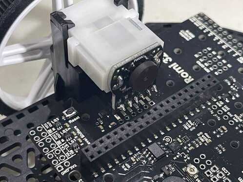
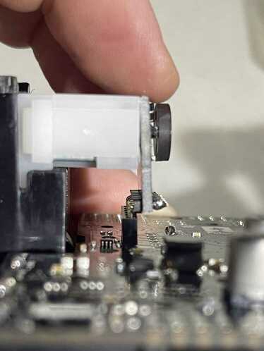
Note: You might think the pins and stand-off for the motor encoder/power source are not plumb with the board. You're correct. This is partly my lack of a steady hand, and partly because it seems to just work out this way. I saw a few images of people mounting the pins outwards in the other set of holes, but I opted to go with the examples shown in all of the Pololu tutorials and photos.
Software
Software is broken up into two categories: everything that runs on the Raspberry Pi, and the code flashed to the Control Board. The Raspberry Pi will be doing almost all the work, given it is a far more powerful computer. The Control Board will be responsible for the execution of larger commands. For example, the Pi will tell the Control Board "turn left" and the board will translate that command into the required electrical operations that send electricity through the motors in the correct direction.
Raspberry Pi
Installing Raspberry Pi OS
The Raspberry Pi Imager makes this completely painless. It will:
- Download the desired OS (Raspberry Pi OS Lite 32-bit)
- Format and properly partition an SD Card then install the above OS
- Allow you to set things such as the Wifi credentials, the local hostname for the device, and an ssh password.
When using the Imager, make sure you use:
- Pi OS Lite 32-bit
- Set the hostname (eg.
minibot) - Set the Wifi Credentials
- Set a username and password
Note: You MUST use the 32-bit version of Pi OS (other OSes might work, but they must be 32 bit). This can make some operations a bit slower, but there are currently no 64-bit drivers for the Pi Camera 2 that I could find.
You'll pick the SD card that you've plugged into the computer. It might suggest it is completely wiping one or more partitions on this card. That's fine.
Once the imaging is complete, you can remove the card and plug it into the Raspberry Pi. Note that when you boot up the Pi for the first time, it can take 5-10 minutes before it responds to ping or ssh.
Connecting to the Raspberry Pi
If you set the hostname and Wifi credentials correctly, you can address it on the same network with:
ping pihostname.local (where you replace pihostname with the hostname you picked)
Note:
pingis a command that sends a tiny packet of data over the network that requests a tiny response. It's a way to say "hello!" and prove that your two computers can communicate.
Once that works, you can ssh to the robot using:
ssh username@hostname.local
It will ask a few security-related questions which you can say yes to. It will then ask for a password.
Installing OpenCV
You now need to set up a few things to get the Camera working and OpenCV installed.
sudo raspi-config                # Go to "Interface Options" and enable "Legacy Camera". You'll have to reboot after.
sudo apt update                  # Update the list of available software to make sure you download the latest versions.
sudo apt install python3-opencv  # Install OpenCV for Python 3.